Make your own controller
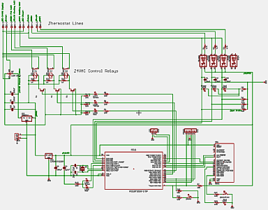
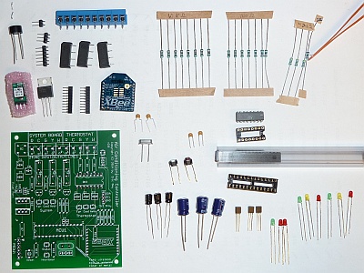
These are the plans, bill of materials, and firmware necessary to build your own HVAC controller. Please be aware that I am a self-taught hobbyist in electronics and HVAC and I do not warrant my designs and implementation fit for any particular application. There are likely design flaws and software bugs lurking herein. You take full responsibility for hacking your air conditioner and playing with electricity.
Bill of materials: bom.csv
Controller firmware: etdey/hvac-controller
Server Software
Although the controllers are designed to run autonomously without the need for control inputs from a central server, it is useful to transmit operational statistics to a time-series database for visualization and analysis. For my setup, I chose InfluxDB and Grafana for my database and analysis tool.
The central server has an XBee radio module attached via USB and it runs a Python program that receives these status packets from the HVAC controllers at 60 second intervals. This code is responsible for updating the InfluxDB time-series database.
typedef struct {
    uint8_t packetType;
    uint8_t versionMajor;
    uint8_t versionMinor;
    uint8_t sequenceNumber;
    unsigned long uptime;
    uint8_t systemState;
    uint8_t thermostatState;
    uint8_t currentState;
    uint8_t targetState;
    unsigned long timer_fanOn;
    unsigned long timer_fanOff;
    unsigned long timer_coolOn;
    unsigned long timer_coolOff;
    unsigned long timer_heatOn;
    unsigned long timer_heatOff;
    unsigned long accum_fanOn;
    unsigned long accum_fanOff;
    unsigned long accum_coolOn;
    unsigned long accum_coolOff;
    unsigned long accum_heatOn;
    unsigned long accum_heatOff;
    char nodeName[21];
} XBeeStatusPayload;
Data Packet Payload
packetType is always 1. There is only one type of packet currently.
versionMajor and versionMinor contain the firmware version information.
sequenceNumber increments by one for every transmitted packet and rolls over from 255 to 0.
uptime is how many seconds the controller has been running since last reset. Internally, the controller tracks time as a 64-bit number where the first 32-bits count seconds and the other 32-bits count nanoseconds -- the fractional part of the next whole second.
systemState is a bitmap of the current control lines that the HVAC unit is receiving.
thermostatState is a bitmap of the current control lines that the thermostat is sending.
currentState is an enum of the current FSM state.
targetState is an enum of the desired FSM state once minimum time values and other constraints have been satisfied.
timer_* values record the total seconds that the controller has been continuously asserting a control function. For example, if the fan has been on for 15 minutes, timer_fanOn=900 and timer_fanOff=0.
accum_* values record the total seconds during the interval since the last report that a control function was asserted. For example, if the fan was on for the first 40 seconds of the reporting period and then turned off, accum_fanOn=40, accum_fanOff=20, timer_fanOn=0, and timer_fanOff=20 in the status report.
Lessons Learned and Improvement Ideas
These are notable design and implementation lessons learned from this project.
- Do not use floating point numbers as accumulators. While a
doublemay seem to be an easy way to track fractional accumulators such as elapsed time driven by a 100Hz interrupt, they will drive you crazy because the floating point representation will produce unacceptable artifacts due to error propagation. - Beware of rounding and take precautions to eliminate odd behavior. Any time you convert from a high-precision counter that represents values between 0 and 1, take care that you prevent oddities such as the sum of two exclusive accumulators not being equal to the total length of the interval in which they were measured. Example:
accum_fanOn + accum_fanOff == 61for a one minute measurement interval. - Do not trust unshielded I2C cables. If you read the I2C handling firmware code, you will notice that I implemented a watchdog function where the I2C master can arm a WD timer that is reset by a subsequent I2C read. I did this as a guard against and recovery from the controller circuit and/or the Raspberry Pi losing sync with each other. The watchdog worked. It would kick in every few days with one controller/RPi pair and was never triggered with the other pair. The debug logs on the RPi showed that the transmission had missed some bits and hung until the watchdog reset the MCU. The best theory that I could come up with was the the unshielded cable, its particular length, or other electro-magnetic noise in the deployed area made it susceptible to interference.
- Monitor control states to ensure correctness. In one of the 2.0 controller boards, I discovered that the
COOLfunction was being asserted continuously. The K2 relay was occasionally sticking in a closed state after the coil voltage was removed. While I added R20, R21, and R22 as insurance against a stray voltage holding the relay closed, the ultimate problem was that I had a defective relay. In a future improvement, I would include the ability for the MCU to monitor the actual state of the output lines so that it could detect a mismatch between the desired and actual states. - Work up the nerve to have your PCB manufactured before you hand wire and solder the second prototype onto perfboard. While it was useful to build the first prototype like this, I never should have done two boards in this way.
- Test subsystems and core functions on a bread board or perf board before you combine them into a more complex circuit. Unit test modules before they are combined into larger programs so that you can detect design flaws early.
- Ground loops are a rookie mistake. A ground plane on a PCB eliminates many gremlins.
- Get a real multimeter instead of using one made for basic home electrical work. An accurate analogue meter is better than an inaccurate digital one.
These are possible improvements to be made in the future or on the next versions of the controller board.
- Use one larger capacitor between the bridge rectifier and the step-down buck and eliminate the other caps downstream of two power regulators.
- Make a jumper terminal that would allow the measurement of the total DC current through the circuit.
- Enhance the XBee packet handling code to allow command packets to be sent from a central server to the controllers. This would allow for coordination of activities, web-based control UI, and integration with other IoT ideas that I have.
- Add monitoring of the actual control line states in order to detect situations like I described with the stuck relay.
- Put a fuse after the bridge rectifier.
- Battery module or a power-fail state save to EEPROM. Sampling the voltage just downstream of bridge rectifier or using one of the optoisolator channels to monitor the AC power would allow for a power-fail interrupt trigger on the MCU.
- Automatic clock error compensation and saving in EEPROM. This would depend upon being able to send command packets from a central server that has access to an external NTP source.
- Implement the Y2 and W2 second stage functions for HVAC systems that can handle it.
- Look at new and cheaper 802.11 WiFi radio modules that have become available. Probably still needs a server daemon that does database inserts due to code complexity.
- Web based control interface.
- Use an Arduino's ATmega328P as the MCU. When I began this project, I did not realize that you can pull the ATmega328P out of the bulky Arduino board and use it stand-alone in a dedicated circuit. You would probably still want to implement the programming port for easier firmware updates. Otherwise, consider a ZIF socket for it.
- Consider using Elasticsearch instead of InfluxDB. The InfluxDB project went sideways at the beginning of 2015 and Elasticsearch implemented time-series functions.
Previous: Building the controller

