Building the controller
Design Considerations
The goals of this project where to:
- improve the conditioning of the air by controlling humidity and removing hot-spots,
- reduce my electrical bill with more efficient running of the HVAC systems,
- learn about embedded programming with the PIC micro-controller,
- learn about ZigBee wireless mesh networking,
- learn about designing and building electronic circuits.
The design constraints of the solution included:
- software-based control logic; field upgradable
- autonomous operation for core HVAC functions without a central control server
- ability to install in the attic with the HVAC control board
- use an MCU such as the PIC or ATmega -- not a SOC like Raspberry Pi or Beaglebone
- use a wireless radio to communicate with my home server
- use existing thermostats for their user interface, thermometer, and clock
Although I have a fair amount of experience with the Raspberry Pi SOC, the choice of using an MCU came from the desire to reduce complexity with powering the circuit and to increase the system reliability. The RPi, for example, uses a Debian Linux based operating system that utilizes SD flash storage. Since the OS uses flash storage in the same manner as it uses spinning magnetic media, it tends to burnout its SD cards within a few months of continuous uptime. I was also worried about heat in the attic causing a system failure with a complex system like the RPi. Lastly, I wanted to learn more about using MCUs.
Residential HVAC system use 24VAC for their control functions. This 24VAC powers the thermostat on the wall and the thermostat uses that voltage to assert the control lines to turn on the fan, cooling, and heating functions. A logical choice of the design was to use the readily available 24VAC to power the control circuit. An MCU like the PIC could be easily powered with a custom-made voltage rectifier and DC power supply.
The requirement to incorporate wireless communications came from wanting to transmit operational data to a central server and to have the ability to push commands to the controllers. The job of collecting, storing, analyzing, and graphing data from the upstairs and downstairs controllers is better done by off-the-shelf software that runs on Linux. The XBee wireless module was chosen over 802.11 WiFi because of cost (in 2014), its ability to form a mesh network between all nodes, and its host interface. Most cheap 802.11 modules require a heavy-weight driver to be installed onto Windows or Linux and are not suited for the UART/I2C/SPI interfaces available on MCUs. (Update: At about $5, the ESP8266 WiFi module might be an alternative to the XBee.)
In the interest of design complexity, build time, and aesthetics, I chose to use my existing thermostats as the user interface for the HVAC. In addition to their interface buttons and display, thermostats contain a time-of-day clock and calendar and a thermometer. By utilizing the UI, RTC, and thermometer from my existing thermostats, this simplifies the tasks that my controller board is required to perform. By inserting my controller board between the HVAC system and the thermostat, I take input from the thermostat and maintain final authority over the control inputs to the HVAC.

System architecture
Operations
The operational logic of the controller is software controlled and is based on some key rules.
- Attempt to first use the fan to hit a target temperature.
- Run the cooling and heating functions long enough to thoroughly condition all the air in the space.
- Prevent cooling and heating hysteresis.
These rules are achieved by imposing minimum times between the state transitions shown in the finite state machine diagram. The FSM graph shows the transitions (edges) that the controller implements versus the transitions that a typical thermostat implements.
The controller also adds a pair of new states that do not exist in a normal thermostat: "Cool OFF, Fan ON" and "Heat OFF, Fan ON". The purpose these two additional FSM states is to provide additional transitions from the time when the cooling or heating function is active to when the system can transition to "All OFF" or to another conditioning function. This first transition out of the conditioning function is where the minimum run time is imposed. The next transitions control how long the fan must run after the conditioning function has ended. An example of this is that the fan runs for a few minutes after cooling has turned off in order to blow air through the cooling coil since it remains cold for a period of time after the condenser stops pumping freon through it.
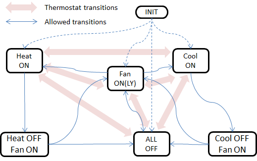
Controller's State Machine
Prototype to 2.0
I selected the PIC18F25K20 microcontroller as the basis for my project. It is an 8-bit MCU with a decent number of GPIO ports, I2C and UART ports, 32KB of program storage, and it sells for $2.54 each from Digi-Key Electronics. I chose the SPDIP package configuration since this allows for experimentation on a breadboard and hand-soldering of a socket for the chip.
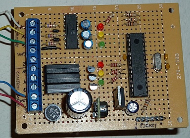
After learning how to program the MCU with Microchip's MPLAB X IDE and after experimenting with crucial parts of the final circuit on a breadboard, I ordered a pile of parts from Digi-Key, supplemented with random purchases from Radio Shack, and set about the task of hand-soldering everything onto a perfboard. The initial version of the circuit included three digital inputs to read the thermostat, three digital outputs to control the HVAC system, and an in-circuit programming port for the PICkit for uploading new software onto the MCU. Later, I added a reset button and an I2C port.
The second prototype was modeled after the first and was also hand-soldered onto perfboard. Since these prototypes lacked communications radios, I used one Raspberry Pi per controller connected through their I2C ports. Each Raspberry Pi ran a sampling script to query its controller and transmit the results over WiFi to a database server.
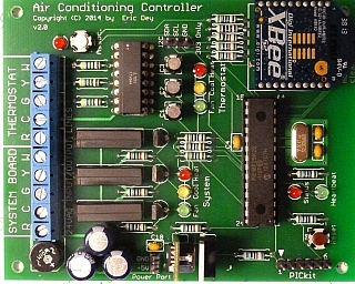
For the version 2.0 controller board, I designed the printed circuit board in Eagle CAD and used a custom PCB manufacturing company to create it. This gave me the ability to incorporate the mounting holes and wiring for an on-board radio module. The custom PCB vastly reduced the soldering complexity and time. First, there were no wires to cut, strip, and solder. Second, the components had holes specifically placed and customized for them. Even though the custom PCB had more components, soldering took less than an hour while the original prototypes had each taken nearly a day to assemble.
The 2.0 controller board retains the I2C port from the prototype because it allowed me to take my time writing the packet handling software for the ZigBee radio module. There is also a 5VDC power port that powered the Raspberry Pi that was initially using the I2C port. Once I finished the packet handling software and included it into the firmware, these two ports were no longer used.
Design Notes
The power supply for the circuit uses a bridge rectifier to turn the 24VAC into pulsed DC voltage that is smoothed with a capacitor. A step-down buck and a linear voltage regulator are then used to create the regulated 5VDC and 3.3VDC outputs that are used by rest of the circuit.

Power supply design
While the second and third capacitors at the 5VDC and 3.3VDC outputs are probably not necessary, they were cheap insurance against power gremlins in the circuit. Since I do not have access to an oscilloscope, I could not analyze the stability of the outputs during operations to see if the capacitors were extraneous.
The 3.3V linear regulator must have a low drop-out voltage since VIN is 5V from the step-down buck. I chose the T.I. LM1086-3.3 because its drop-out voltage is about 1.3V. Since the voltage difference between VIN and VOUT is small, the linear regulator does not need to shed much operating power as heat and runs fairly efficiently.
A thermostat controls an HVAC system by asserting the FAN, COOL, HEAT lines with 24VAC in order to turn on a function. I used the LTV-844 photocoupler in order to isolate the 24VAC from the 3.3VDC input to the PIC microcontroller. Internally, the LTV-844 uses a pair of parallel, opposite-polarity LEDs per channel in order to detect both phases of the AC voltage.
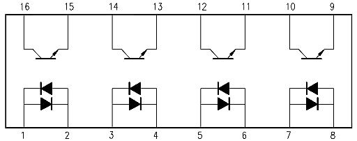
Optical isolation for thermostat sampling
The collectors of the photo-transistors on the output side of the LTV-844 (pins 9-16) are supplied with 3.3VDC. When the thermostat asserts an input channel (pins 1-8), the LEDs light and saturate the base of the photo-transistor causing the 3.3VDC current to flow to the corresponding emitter which is connected to a digital input pin of the microcontroller. Since there are only three inputs (FAN, COOL, HEAT) in this circuit, the fourth channel of the LTV-844 is not used.

The HVAC control lines are asserted by the microcontroller through a relays whose coils are powered by the 5VDC. The microcontroller uses its 3.3VDC digital output pins to saturate the bases of NPN transistors whose collectors are attached to the 5VDC and emitters are attached to the relay coils.
Previous: About the project
